Ethernet module for controls with optocouplers and relays
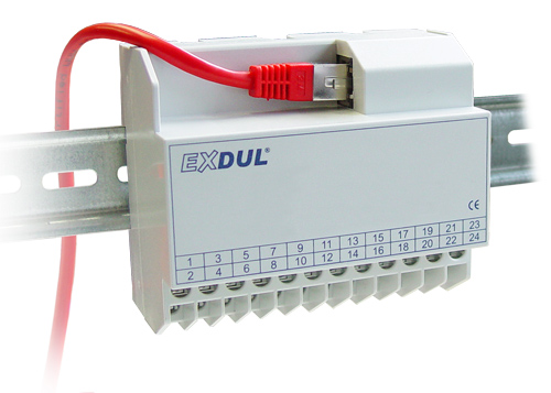
EXDUL-537S
- 12 optocoupler inputs
- 8 relay outputs 2A
- 6 counters
- Programmable logic
- Module initiated message
- watchdog
- webserver/webpage
- 100Base-T Ethernet interface
EDP number: A-375420
Bipolar inputs with optocouplers and power outputs via relays
The inexpensive EXDUL-537S Ethernet module for controls with a 100Base-T Ethernet interface has 12 digital bipolar optocoupler inputs and eight power relay outputs with electrical isolation. The optocoupler inputs are secured with additional overvoltage protection diodes. The switching current of the relays is a maximum of 2 A per channel. Contact A of the relay is connected to one terminal each, contact B is brought together on a common terminal for all 8 channels.
Optocoupler inputs can be used as counters
If required, six of the 12 optocoupler inputs can also be used as hardware-supported 32-bit counter inputs with a maximum input clock of 5 kHz. To prevent meter data loss in the event of a power failure, the meter readings are saved in the module at intervals of 100 us and automatically loaded into the meter register when the module is restarted.
Webpage
The module can be configured in a user-friendly manner via the integrated web page. In addition, simple function tests such as reading in the inputs and switching the relays are also possible.
Communication via TCP/IP connection
The communication between the PC and the module takes place by sending and receiving byte arrays via the 100Base-T Ethernet interface.
Watchdog
The EXDUL module has security mechanisms for stable communication between the module and the PC. However, if communication is interrupted, e.g. due to routing problems, and the connection can no longer be reestablished, the module's integrated watchdog timer can be used to troubleshoot the problem.
Internal logic with module initiated messages
In various applications it can be advantageous if the module reacts independently to input signals or changes at the inputs. Without this option, a change at the input can only be detected by regularly querying the inputs using polling. This polling causes an increased load on the network and the computer. In order to generate this independent reaction of the module, four logic branches are provided, each with four logic inputs, a link and a logic output. This logic output can then be connected to a relay output or used for module-initiated messages to the PC.
External power supply
The module is supplied with the necessary operating voltage of between 10 and 30 volts via an external voltage source.
Connection and assembly
The connections for the power supply, like the connections for the input optocouplers and output relays, are fed to a 24-pin screw terminal strip. The compact housing allows use as a mobile module on the notebook and as a control module in control and mechanical engineering with simple wall mounting or uncomplicated mounting on DIN EN mounting rails.
Software, drivers, programming languages
No additional driver is required for the EXDUL-537 Ethernet module. A prerequisite is a provided network connection from the PC (network card with driver) or mobile device. The TCP/IP libraries available in many high-level languages such as C, C++, C#, Visual Basic or Java are required for direct access to the module.
Supported operating systems and programming languages
Microsoft Windows®
Java®, VB.net®, C++.net®, C#.net®, Python®, Labview Tutorial®
Linux®
C®, C++®, Java®, Phyton®
Android®
C#®